Getting the MIPI DBI screen for the Sipeed M1S dock to work on Linux

Background
What started out as an activity to clear out unused stuff from my cupboard led on to a small project to get Linux working with the MIPI DBI screen for the Sipeed M1S dock.
I first got hold of the Sipeed M1S dock back in December 2022. What tempted me was the rich set of features it supports, all in a really small package -- NPU, WiFi/BT/Zigbee, 3 RISCV cores courtesy of the BL808 SoC from Bouffalo Labs. It was also touted as being able to run Linux owing to one of its RISCV cores having an MMU. Beyond playing around with the SDK and a few examples, I didn't venture further due to poor documentation. Quickly, it went back to a box I've conveniently dedicated for dev boards which were marketed to support all kinds of features but disappointingly lack good documentation and were thus chucked aside until I had more time to mess around.
That time finally came, in a period when work has gotten mundane and I needed some mental stimulation. In the process of decluttering my cupboard, I got reunited with the Sipeed M1S dock and there begins the journey of bringing that up again.
I was curious to see how far the Linux support has come. Back then, the Linux set-up from Bouffalo Labs has largely been a nice proof-of-concept. It boots. You get a shell prompt in the end but nothing more. WiFi was not working. I was delighted to find out that WiFi is now working on Linux with the buildroot image shared by Bouffalo Labs as well as that by OpenBouffalo (a community centred around Bouffalo Labs SoC).
It's nice when things seem to just work now but my itch for working on something new has not been alleviated. That was when I thought it will be cool to get the display on the Sipeed M1S dock working with Linux, and no one seems to have publish about getting this to work. Hence, the reason for this post.
Note: If you're not interested in how I got this to work, you can simply ignore the rest of the content and see my fork of OpenBouffalo's buildroot here. You can get the build artifacts from the CI pipeline (if they have not expired) or you could clone the repo and build it yourself locally.
Where do we even start?
First, let's consider what we do know:
- The Bouffalo Labs kernel tree already has the driver for the SoC's SPI module: https://github.com/bouffalolab/linux-dev/commit/408a11c49a7600d97cbf37391e689af7d3b6b74b.
- The screen is manufactured by polcd.
- The display controller is ST7789V as noted in the link above.
- The display controller ST7789V can operate in parallel mode or serial mode. In the case of the Sipeed M1S dock, the 8-bit 4-wire serial mode is used.
The 4-wire serial mode uses 4 pins of the SoC. They are:
- SDA: The data pin. It is both an input and output pin. Primarily, we'll be using it as an output pin as all we care about is to send command bytes and pixel data bytes to the display controller so that it could populate the framebuffer on our behalf.
- SCK: The clock pin.
- DC: The data/command pin. It should be pulled low while the command byte is sent and then pulled high while the parameter data bytes accompanying the command are sent out.
- CS: Typical SPI chip select pin. Active low.
Other pins involved are the LCD reset pin (active low) and the backlight pin.
The SPI configuration to be used with the ST7789V display controller is CPOL of 0 and CPHA of 0, i.e. idle clock level of low and shifting data in at the falling edge of the clock and sampling at the rising edge.

Now, with those preliminaries out of the way, can we at least toggle the backlight somehow from userspace? From the schematic, one can see that the backlight is connected to GPIO 11 pin of the BL808 SoC. We'll ignore driving it using PWM for now and simply focus on turning it on or off.
Fortunately, the original buildroot image from OpenBouffalo already includes the gpio set of utilities, and the gpio driver is also built into the kernel. This enables us to play around with the gpio from userspace. All we need to do is execute gpioset /dev/gpiochip0 11=1. Doing so indeed lit up the backlight as expected.
# gpioinfo
gpiochip0 - 46 lines:
        line   0:      unnamed       kernel   input  active-high [used]
        line   1:      unnamed       kernel   input  active-high [used]
        line   2:      unnamed       kernel   input  active-high [used]
        line   3:      unnamed       kernel   input  active-high [used]
        line   4:      unnamed       kernel   input  active-high [used]
        line   5:      unnamed       kernel   input  active-high [used]
        line   6:      unnamed       unused   input  active-high
        line   7:      unnamed       unused   input  active-high
        line   8:      unnamed       kernel   input  active-high [used]
        line   9:      unnamed       unused   input  active-high
        line  10:      unnamed       unused   input  active-high
        line  11:      unnamed       unused   input  active-high
        line  12:      unnamed   "spi0 CS0"  output   active-low [used]
        line  13:      unnamed       unused   input  active-high
        line  14:      unnamed       unused   input  active-high
        line  15:      unnamed       unused   input  active-high
        line  16:      unnamed       kernel   input  active-high [used]
        line  17:      unnamed       kernel   input  active-high [used]
        line  18:      unnamed       unused   input  active-high
        line  19:      unnamed       kernel   input  active-high [used]
        line  20:      unnamed       unused   input  active-high
        line  21:      unnamed       unused   input  active-high
        line  22:      unnamed       unused   input  active-high
        line  23:      unnamed       unused   input  active-high
        line  24:      unnamed       unused   input  active-high
        line  25:      unnamed       unused   input  active-high
        line  26:      unnamed       unused   input  active-high
        line  27:      unnamed       unused   input  active-high
        line  28:      unnamed       unused   input  active-high
        line  29:      unnamed       unused   input  active-high
        line  30:      unnamed       unused   input  active-high
        line  31:      unnamed       unused   input  active-high
        line  32:      unnamed       unused   input  active-high
        line  33:      unnamed       unused   input  active-high
        line  34:      unnamed       unused  output  active-high
        line  35:      unnamed       unused  output  active-high
        line  36:      unnamed       unused   input  active-high
        line  37:      unnamed       unused   input  active-high
        line  38:      unnamed       unused   input  active-high
        line  39:      unnamed       unused   input  active-high
        line  40:      unnamed       unused   input  active-high
        line  41:      unnamed       unused   input  active-high
        line  42:      unnamed       unused   input  active-high
        line  43:      unnamed       unused   input  active-high
        line  44:      unnamed       unused   input  active-high
        line  45:      unnamed       unused   input  active-high
# gpioset /dev/gpiochip0 11=1

The next thing then is to delegate the task of backlight control to a kernel-space driver and get it working with the drm subsystem. The kernel already has a generic gpio-backlight driver upstream. Perhaps, we could utilise that? Short of reinventing the wheel, is there an existing ST7789V display controller driver we could use?
Drivers
A quick search on the web shows that there are two drivers already in the mainline kernel which could work -- (1) panel-sitronix-st7789v and (2) fb_st7789v. The latter is in staging and uses the deprecated fbdev framework so that is not recommended. Whereas the former uses the more modern drm framework; that was what I started with. It is not immediately obvious it will just work out of the box. After much time investigating why it wouldn't work with the correct device tree, I realise it's written to use the parallel RGB interface from the start: see https://github.com/torvalds/linux/commit/7142afb3a186ed2cd028318205a4852f04283380; I didn't explore further if that is true with the latest version.
In the end, I stumbled upon panel-mipi-dbi. It's pretty well-documented. All I need is to write the display initialisation sequence and convert this to binary so that it could be read by the panel-mipi-dbi driver as a "firmware" blob.
The "firmware" blob
The polcd datasheet is pretty sparse with details, lacking information about the display initialisation sequence to be used. As such, I basically took what was in the Sipeed M1s SDK and adapted that while cross-referencing with the ST7789V datasheet to satisfy my curious mind on what is going on behind the scenes. The following is the initialisation sequence used:
# From components/platform/soc/bl808/bl808_std/BSP_Common/lcd/spi/st7789v_spi.c
# from https://github.com/sipeed/M1s_BL808_SDK.git

command 0x01

delay 120

delay 120

command 0x11

delay 120

command 0x3A 0x55

delay 120

command 0x21

delay 120

command 0x29

command 0x36 0x60

command 0xC6 0x00
The delay values are not an exact replica of those found in the SDK. Those in the SDK are 6us which I felt could be a little too short; I've thus inflated them to 120ms mostly for good measure. I then used the script from here to generate the binary blob.
I've opted for the panel-mipi-dbi driver to be built-into the kernel rather than a kernel module so that it could be used from boot. However, this means the blob it references will also need to be built-into the kernel as the rootfs is not yet mounted at the start and /lib/firmware is not accessible. The other option is to include the blob in the initramfs; I did not pursue this option.
Another thing to note is that the blob has to be named the same way as the first compatible string in the display device node in the device tree. See the following snippet from https://github.com/gregkh/linux/blob/799441832db16b99e400ccbec55db801e6992819/drivers/gpu/drm/tiny/panel-mipi-dbi.c#L139-L150:
static struct panel_mipi_dbi_commands *panel_mipi_dbi_commands_from_fw(struct device *dev)
{
	struct panel_mipi_dbi_commands *commands;
	const struct firmware *fw;
	const char *compatible;
	char fw_name[40];
	int ret;


	ret = of_property_read_string_index(dev->of_node, "compatible", 0, &compatible);
	if (ret)
		return ERR_PTR(ret);
...
...
...
Working finally?
Now that we got the correct device tree, display driver and the accompanying blob integrated into buildroot, everything should be working right? Sadly, no.
The display backlight wasn't even lit up at boot. There was however a "spi: deferred probe pending" line in the kernel message log. That should be enough to lead us further. That line basically tells us that the driver is waiting for other drivers to be available. But, what could it possibly be waiting for? To make debugging easier, I've chosen to make the panel-mipi-dbi driver a kernel module temporarily. That should allow me to easily see what is going on with the help of debugfs.
Doing the following provided a further clue:
# mount -t debugfs none /sys/kernel/debug
# echo 'panel-mipi-dbi.c +p'>/sys/kernel/debug/dynamic_debug/control
# modprobe panel_mipi_dbi
What I saw in dmesg was "Failed to get backlight". It turns out I've forgotten to include the gpio backlight driver in the kernel build; CONFIG_BACKLIGHT_GPIO is not set! What a silly oversight. After enabling that and rebuilding the kernel, the backlight finally lit up at boot!
The euphoria was short-lived though. Nothing was shown on the display after starting X server and launching xeyes.
What went wrong?
This part got me hanging the longest. Could it be a wrong initialisation sequence in the blob? I tried every single thing I could think of: double-checking the ST7789V datasheet, making sure cpol and cpha weren't set in the device tree, among others. However, I don't see anything which stood out as wrong in what I have done so far.
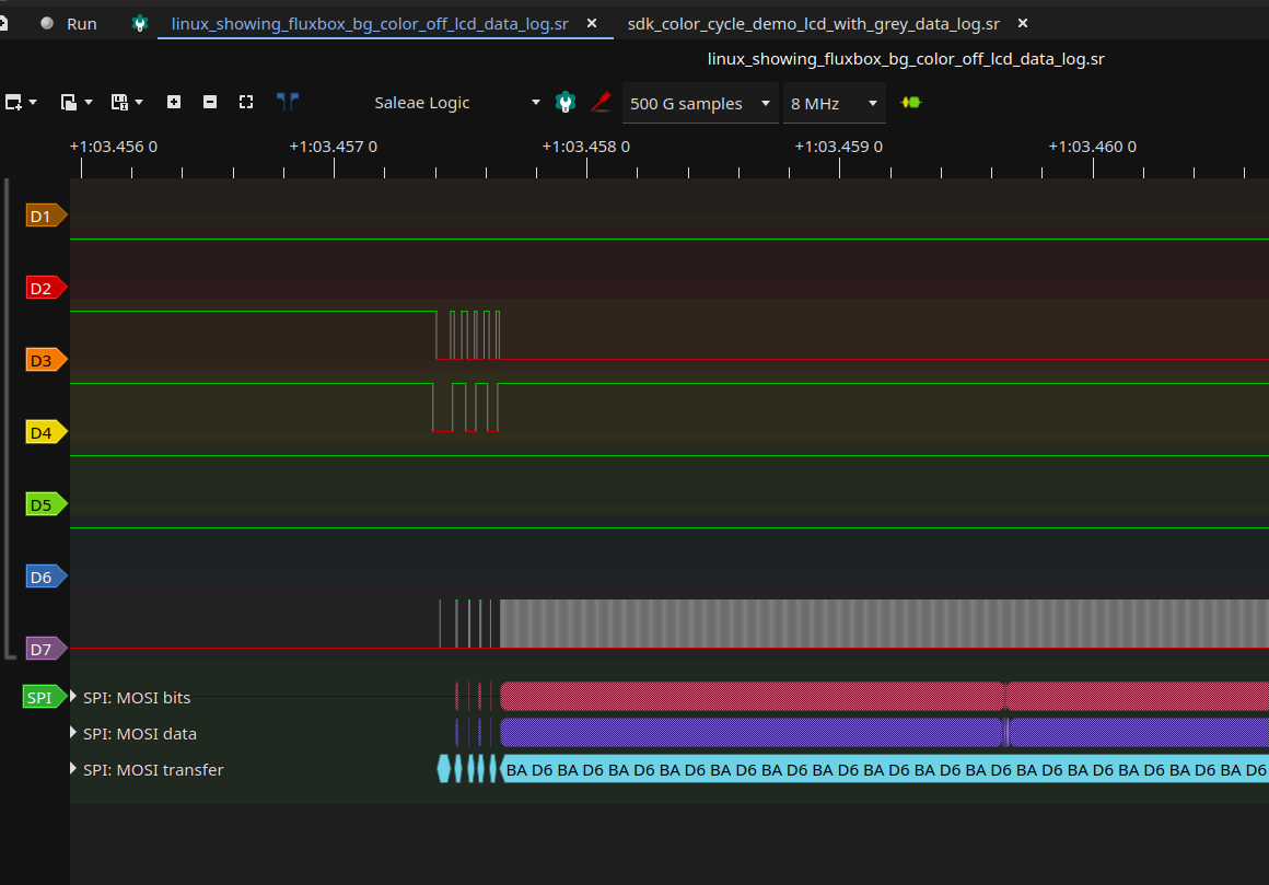
I was stumped. That was when I thought it is time to bring out my logic analyser to see what was truly happening at the physical level. My logic analyser has a max sampling rate of 48MHz so I had to dial the clock frequency of the SPI down from 80MHz (the SoC's SPI module supports a clock frequency of up to 80MHz and the maximum was currently configured in my device tree at that time). Being paranoid, I reduced the SPI clock frequency to 4MHz (reducing more than what was required; remember the Nyquist sampling theorem?). Then, off I went with probing.

Probing the SPI signals
What was immediately obvious is that the CPHA was completely wrong despite being correct at the device tree level. Let's consider the first command byte, i.e. 0x01, in the initialisation sequence shown before.

The last high bit should changed at the falling edge, rather than at the rising edge of the clock. That behaviour is clearly inconsistent with a CPHA of 0 (what the ST7789V display controller chip expects). No wonder it didn't work. Bouffalo Labs's driver seems to be misintepreting the lack of cpha in the device tree as CPHA of 1. To compensate for this and as a hack (mostly because I should be fixing the driver instead), I've specified cpha in the display device tree node.
Rebuilding the kernel and viola! We're getting something now (albeit with a weird truncated view and wrong aspect ratio but nothing too hard to fix).

Weird colours
The colours are still off. The background of fluxbox should be grey. What is with the purple tint? RGB vs BGR order? Selecting the BGR order by sending the MADCTL command byte alongside a parameter byte with the BGR bit set didn't help.

One of the SDK examples is a simple program cycling different colours shown on the display every 1 second. Let's include the specific fluxbox grey in the list of colours it cycles through and see if it displays correctly. The specific grey hex colour code was determined by colour picking the grey fluxbox background as viewed from a vnc client connected to the x11vnc server running on the Sipeed M1S then linearly converting that 24-bit pixel data to 16-bit. The 16-bit value (RGB565: 0xD6BA) was then hardcoded in the SDK example application as an additional colour. Indeed, the grey displayed correctly with the SDK example, with no sign of any tint.
Now, comparing the logic analyser data between those when the SDK example was running and those when fluxbox was running, the answer is obvious. The bytes were clearly swapped. It turns out the drm kernel driver is sending pixel bytes in little-endian order and the display controller is interpreting those bytes as big-endian and storing them in the framebuffer as such. When the display scans out those bytes in the framebuffer, the colour will obviously be wrong.

Can we tell the ST7789V chip to interpret the pixel bytes sent over SPI as litte-endian and convert them to big-endian before storing them to the framebuffer? There is an endianness setting for the RAMCTRL command. That is exactly what is needed; the description and pictorial illustration in the datasheet are spot-on.

Alas, it did not work; adding the command to the initialisation sequence did nothing. I can only guess that the EXTC pin is pulled low as the datasheet specifically mentioned that system function commands (which the RAMCTRL is part of) can't be executed when the EXTC level is low. This is sadly not something which can be easily changed physically.

How then do we modify the panel-mipi-dbi driver to send pixel bytes in big-endian order? I was aware the drm framework has a list of fourcc code representing the various framebuffer pixel formats (https://github.com/gregkh/linux/blob/v6.5.11/include/uapi/drm/drm_fourcc.h). DRM_FORMAT_BIG_ENDIAN seems obvious to be the modifier we want to use. Can we use it?
It turns out to be a lot easier than I initially thought. This block of code from drm_mipi_dbi.c stood out as being relevant and rightly so:
/**
 * mipi_dbi_buf_copy - Copy a framebuffer, transforming it if necessary
 * @dst: The destination buffer
 * @src: The source buffer
 * @fb: The source framebuffer
 * @clip: Clipping rectangle of the area to be copied
 * @swap: When true, swap MSB/LSB of 16-bit values
 *
 * Returns:
 * Zero on success, negative error code on failure.
 */
int mipi_dbi_buf_copy(void *dst, struct iosys_map *src, struct drm_framebuffer *fb,
		      struct drm_rect *clip, bool swap)
{
	struct drm_gem_object *gem = drm_gem_fb_get_obj(fb, 0);
	struct iosys_map dst_map = IOSYS_MAP_INIT_VADDR(dst);
	int ret;

	ret = drm_gem_fb_begin_cpu_access(fb, DMA_FROM_DEVICE);
	if (ret)
		return ret;

	switch (fb->format->format) {
	case DRM_FORMAT_RGB565:
		if (swap)
			drm_fb_swab(&dst_map, NULL, src, fb, clip, !gem->import_attach);
		else
			drm_fb_memcpy(&dst_map, NULL, src, fb, clip);
		break;
	case DRM_FORMAT_XRGB8888:
		drm_fb_xrgb8888_to_rgb565(&dst_map, NULL, src, fb, clip, swap);
		break;
	default:
		drm_err_once(fb->dev, "Format is not supported: %p4cc\n",
			     &fb->format->format);
		ret = -EINVAL;
	}

	drm_gem_fb_end_cpu_access(fb, DMA_FROM_DEVICE);

	return ret;
}
EXPORT_SYMBOL(mipi_dbi_buf_copy);
See the description of swap? It's clear that swap needs to be true for my use case. To cut the long story short, it was found to be false. All that is needed is the following patch:
diff --git a/drivers/gpu/drm/drm_mipi_dbi.c b/drivers/gpu/drm/drm_mipi_dbi.c
index c871d9f09..00548aef2 100644
--- a/drivers/gpu/drm/drm_mipi_dbi.c
+++ b/drivers/gpu/drm/drm_mipi_dbi.c
@@ -1244,7 +1244,8 @@ int mipi_dbi_spi_init(struct spi_device *spi, struct mipi_dbi *dbi,
 	if (dc) {
 		dbi->command = mipi_dbi_typec3_command;
 		dbi->dc = dc;
-		if (mipi_dbi_machine_little_endian() && !spi_is_bpw_supported(spi, 16))
+		if ((spi->bits_per_word == 8 && mipi_dbi_machine_little_endian()) ||
+			(mipi_dbi_machine_little_endian() && !spi_is_bpw_supported(spi, 16)))
 			dbi->swap_bytes = true;
 	} else {
 		dbi->command = mipi_dbi_typec1_command;
Finally
With that coupled with the appropriate device tree, the display is now working under Linux.
All this effort culminated into a buildroot image with minor patches which can be found in my repo here.

Thanks to OpenBouffalo for providing the base buildroot and also Bouffalo Labs for the driver for the SoC's SPI module, without which it will be a lot of more work to get this going.
Comments
Post a Comment